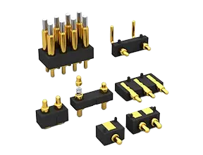
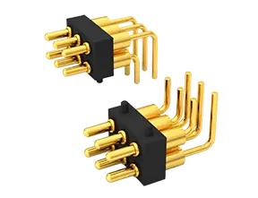
Innovative design: Slope Structure Design, More Stable Contact, Lower Resistance
Installation Method: Surface Mount Technology (SMD) Reflow Soldering
Contact Resistance: 30 milliohms Max.
Rated Current: 2A~30A (Continuous Current)
Rated Voltage: 36V AC/DC
Durability: 10,000~100,000 Times (Reciprocating Motion Lifespan)
Operating Temperature: -40°C to +120°C (Continuous Temperature)
Salt Spray Resistance 96 Hours Corrosion Test
High-Precision Mold And Parts Processing
A variety of standards are available, and samples will be sent out as soon as the same day.
Provide Customized Services
Comply With EU RoHS And Reach Standards
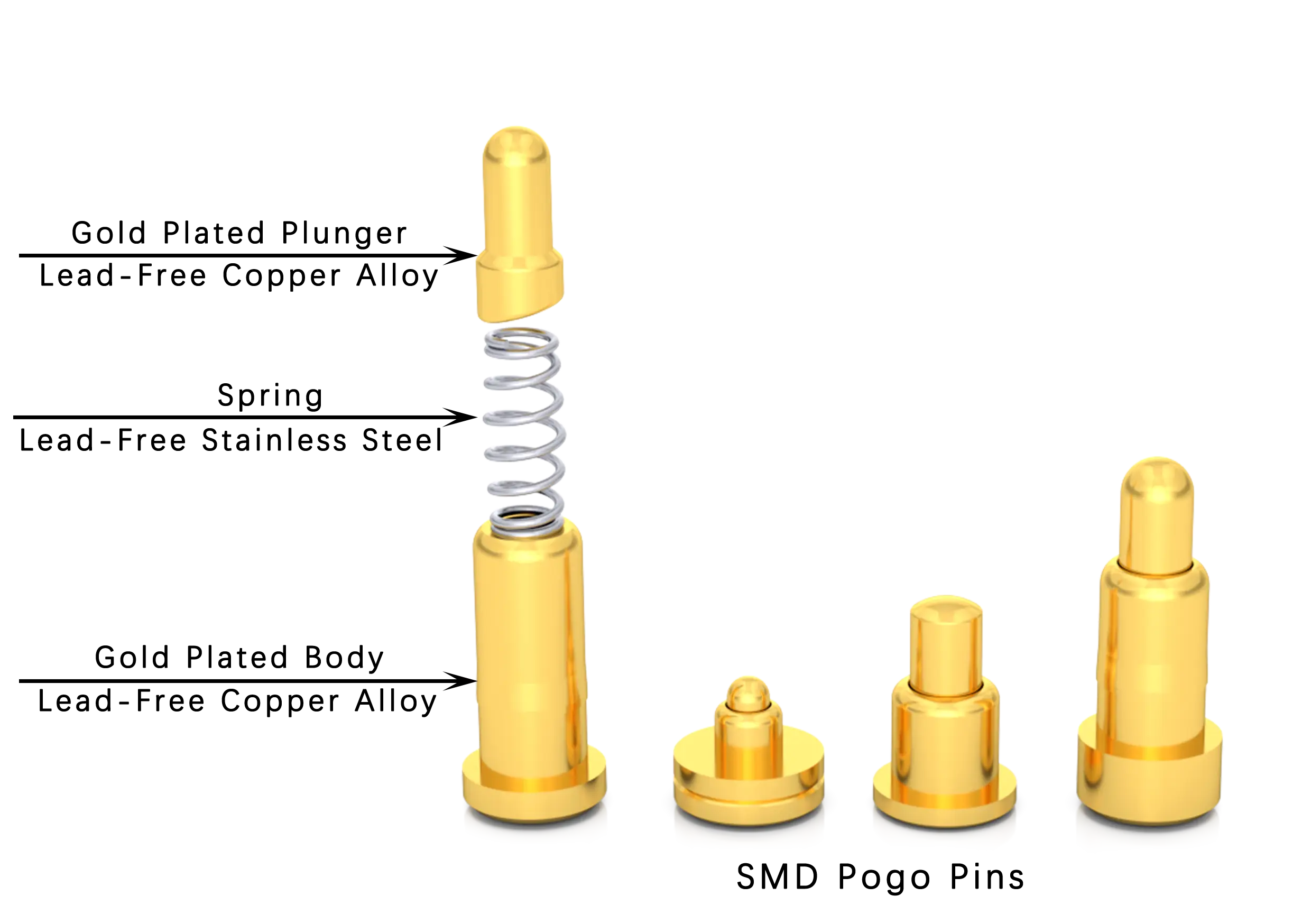
SMD Pogo Pins are precision electronic connectors that are soldered using advanced surface mount technology (SMD). SMD is a common component mounting technology that allows components to be soldered directly to the surface of the circuit board without soldering through PCB circuit board holes. This design advantage ensures low-resistance and high-reliability connections between components and PCBs, which is particularly suitable for electronic products and systems with high-density layouts.
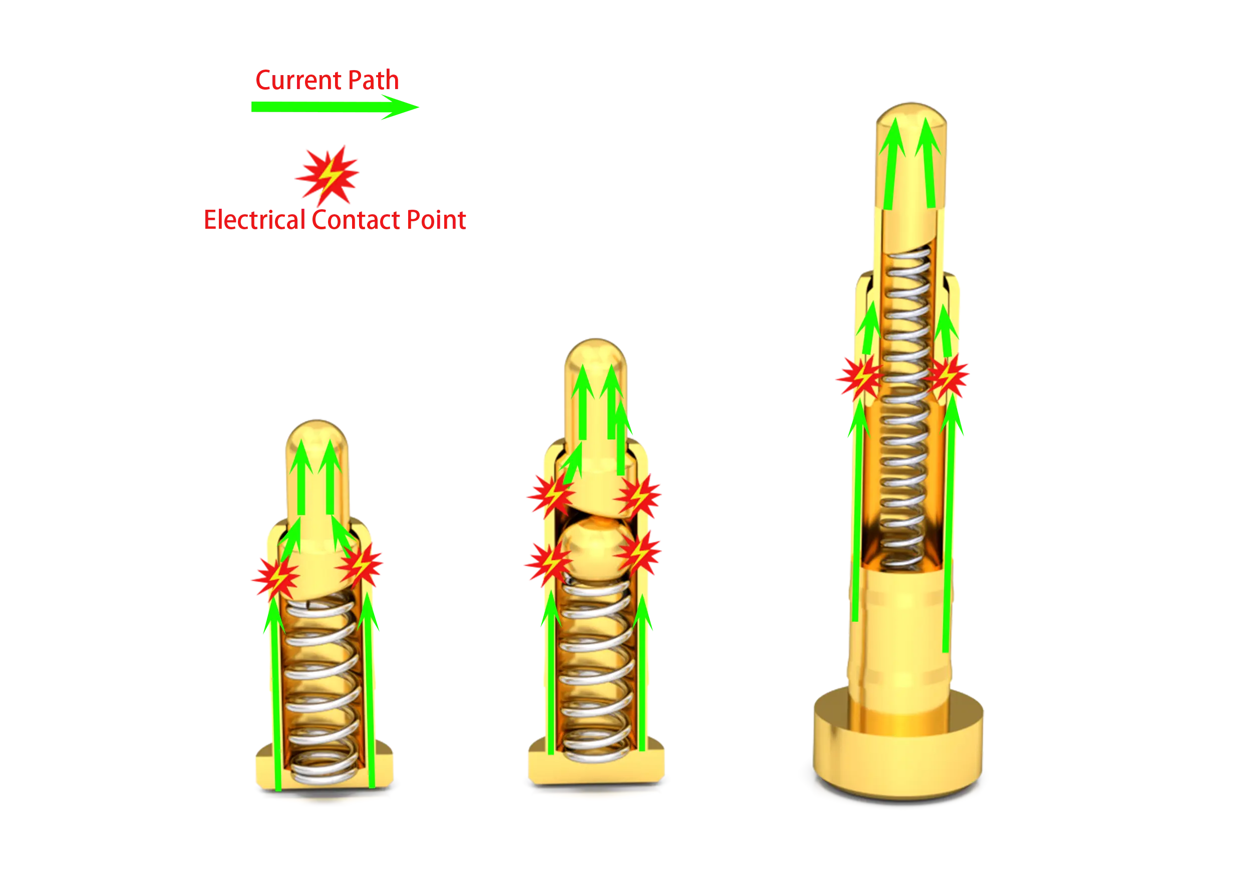
As one of types of pogo pins, SMD Pogo Pins are designed with an italic structure and a built-in spring mechanism. They are mainly composed of three core components: Plunger Spring and Body, and are assembled through precision molds and special equipment. The function of the italic structure design is to ensure that when the Pogo Pins are working, the lateral force generated by the contact between the bevel and the spring is used to maintain stable contact between the needle and the inner wall of the needle tube, prompting the current path to mainly pass through the Gold-Plated Plunger and Body, thereby obtaining extremely low The contact resistance ensures a stable and reliable connection even during frequent plugging and unplugging.
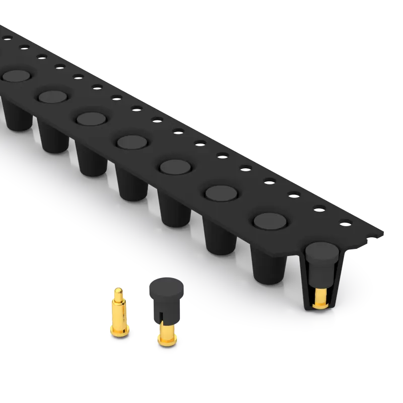
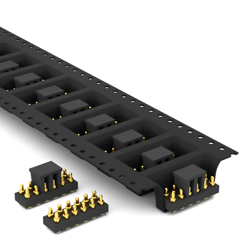
Automatic patch technology: This method uses an SMT patch machine to automatically mount Pogo Pins onto a PCB circuit board with printed solder paste, and then melts and solidifies the solder paste through a reflow soldering process to complete the fixed connection with the PCB pad. This process is fast, accurate and highly automated, greatly improving production efficiency and product quality.
Plastic shell fixing method: Pogo Pins are fixed in the pre-designed inner hole of the plastic shell, and internal and external devices can achieve electrical signal connection through Pogo Pins. The design and application of waterproof O-rings or waterproof glue are used to achieve IPX8 waterproof requirements.
As one of leading pogo pin manufacturers, our SMD Pogo Pins play a key role in the modern electronics industry with their small size, efficient installation and excellent performance. Whether it is consumer electronics, industrial automation equipment, or communication equipment, SMD Pogo Pins are widely used, demonstrating their irreplaceable value and importance.
SMD Pogo Pins is a classification of Pogo Pin connectors. It is a built-in spring connector designed and manufactured based on a bevel structure. It is usually composed of three core parts: plunger, spring and body. It is characterized by a flat pad, very low resistance, stable and reliable contact, long life, beautiful appearance.
There are three commonly used internal structures of Rtench's SMD Pogo Pins, namely Plunger slope structure, Plunger slope + steel ball structure and Plunger inner hole bevel structure.
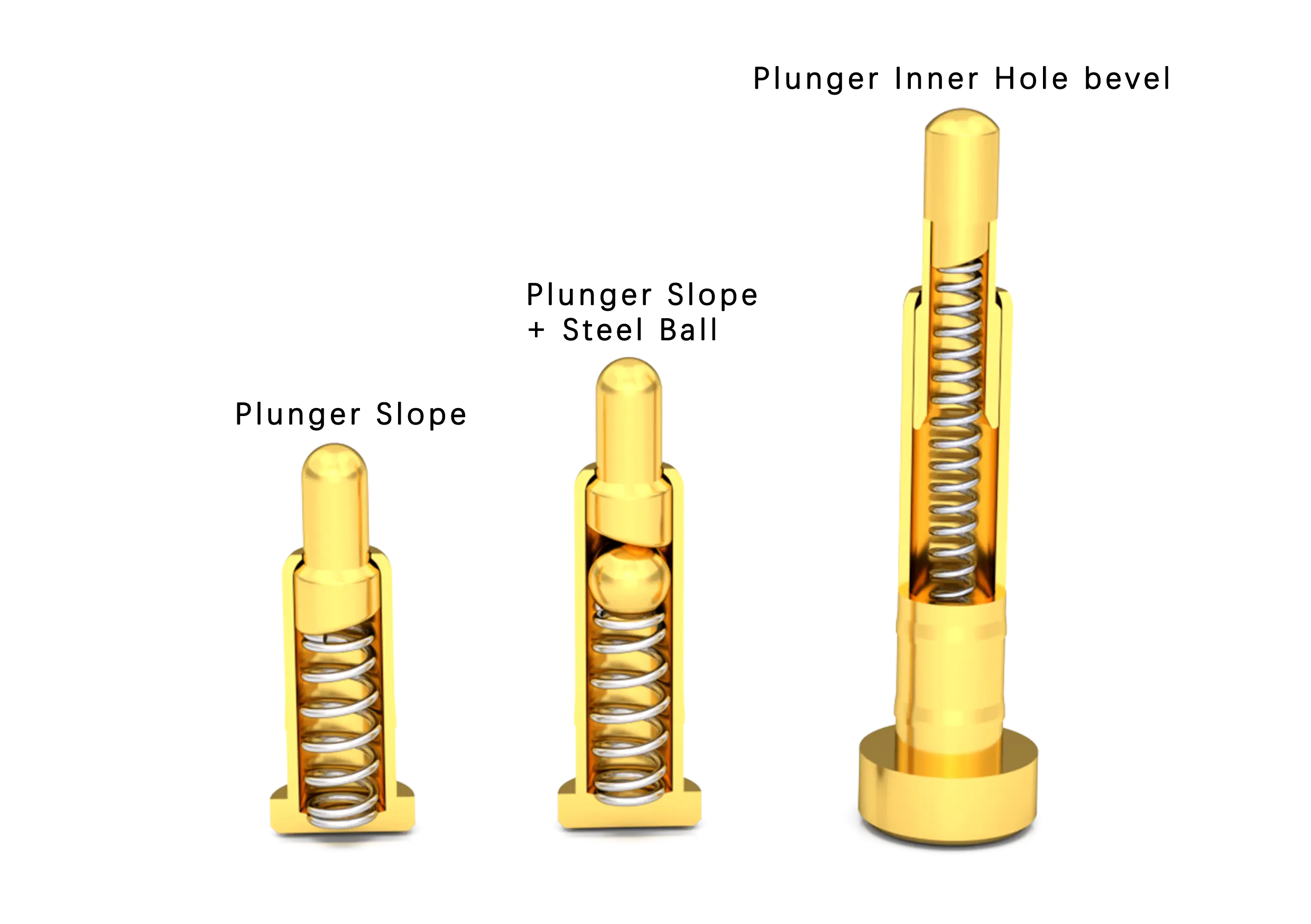
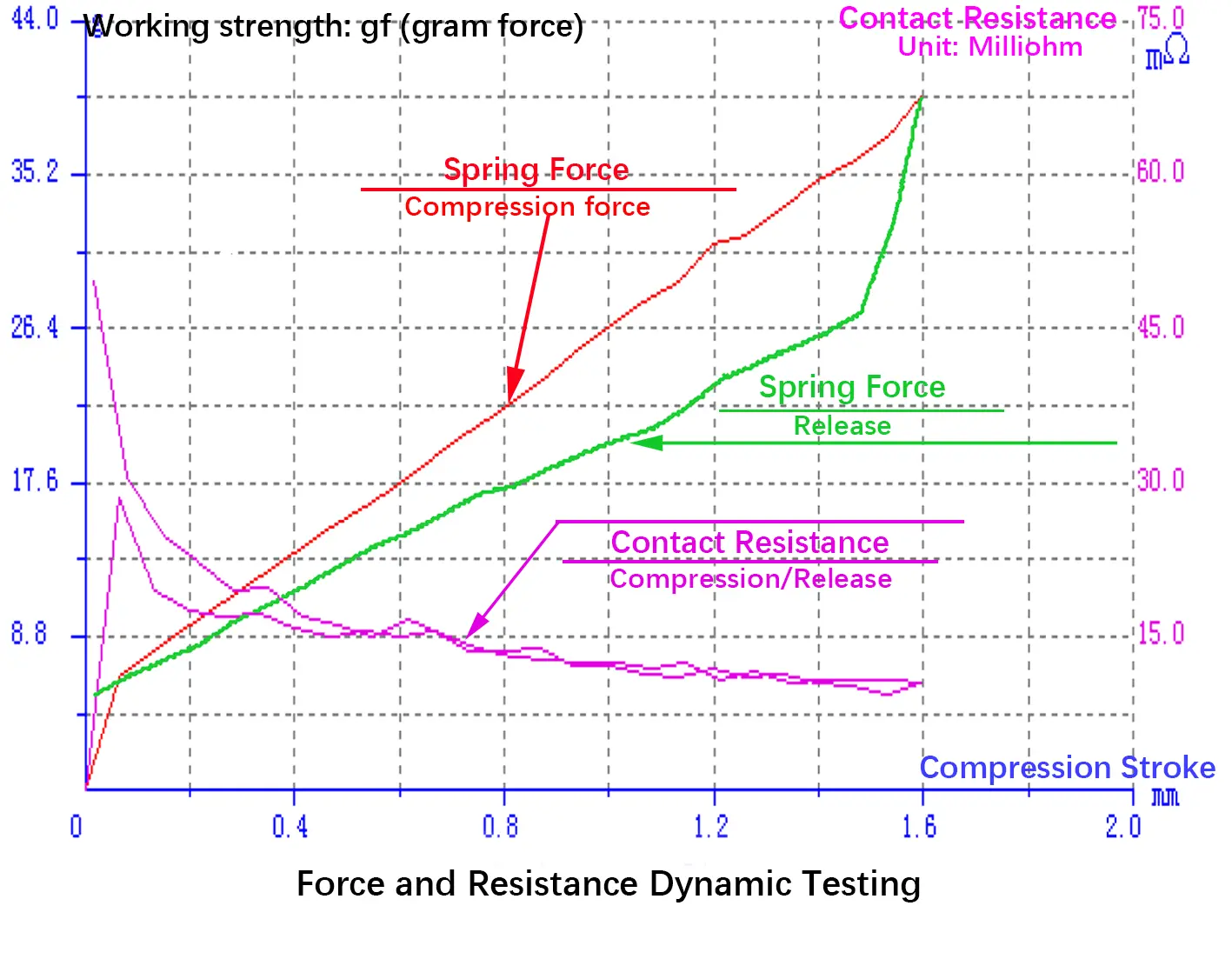
Contact force and contact resistance are the core factors for stable and reliable connections, and there is a direct relationship between contact force and contact resistance. Increasing contact force can effectively reduce contact resistance. Therefore, achieving stable contact force and contact resistance is key to establishing a reliable connection.
When the bevel and spring are working, the lateral force generated is converted into contact force, allowing the gold-plated needle to maintain stable contact with the inner wall of the needle tube, thereby obtaining stable and extremely low contact resistance, ensuring a stable and reliable connection.
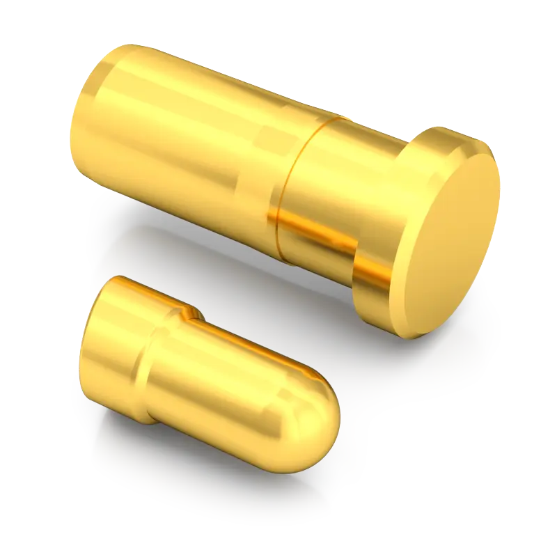
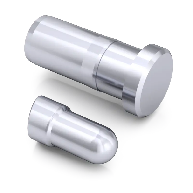
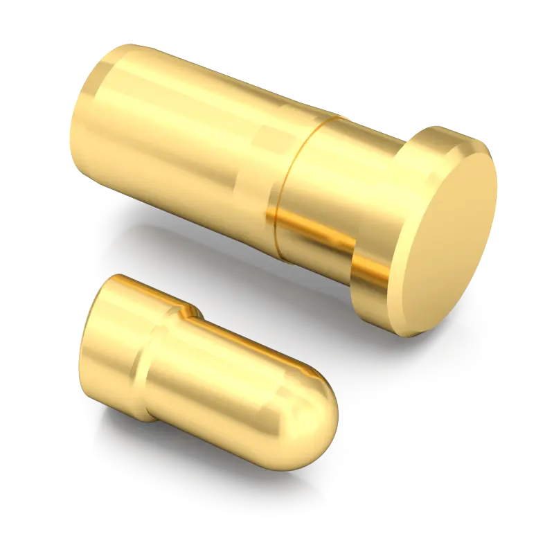
Vacuum blind hole plating technology is known for its excellent performance and can accurately plate a layer of gold inside and outside extremely fine blind holes. This advanced electroplating process not only ensures the overall beauty of the metal surface, but also provides excellent corrosion and wear resistance. Every detail, whether inside or outside the hole, shows a golden and shiny color, and there will be no peeling or gold falling off problems. The precision and stability of this technology ensure the durability and durability of the electroplated layer, meeting a variety of demanding application requirements.
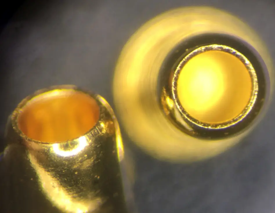
Mature design, high-precision processing and advanced vacuum blind hole plating technology are combined to achieve extremely low and stable contact resistance.
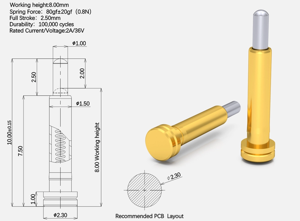
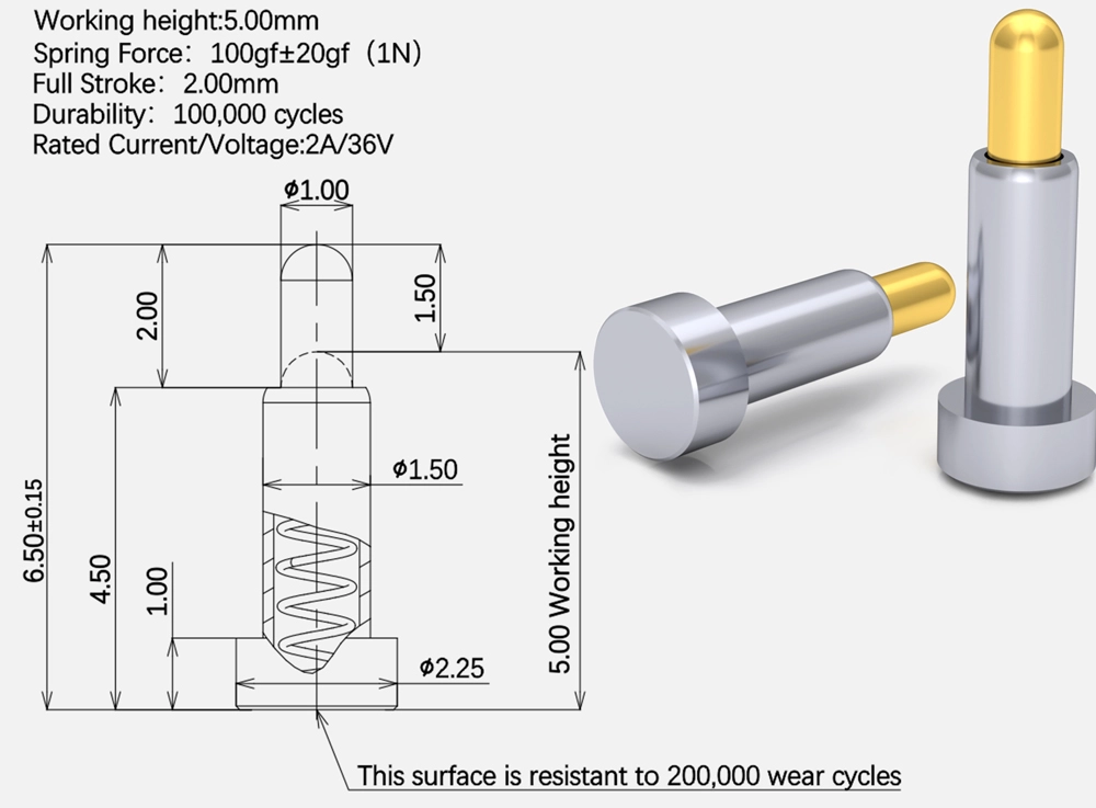
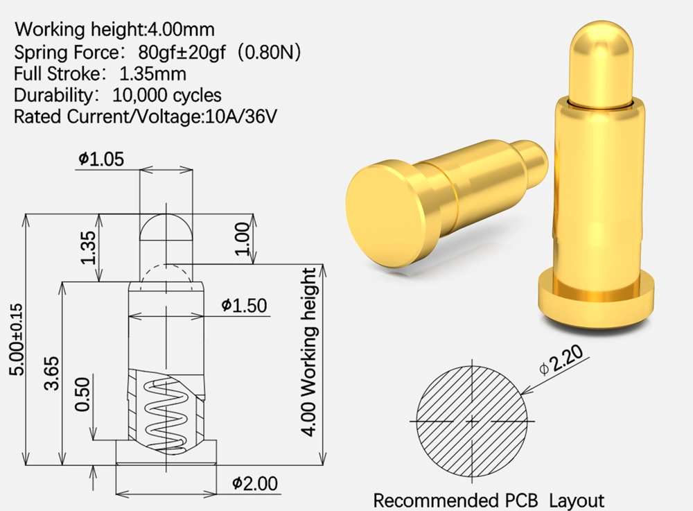
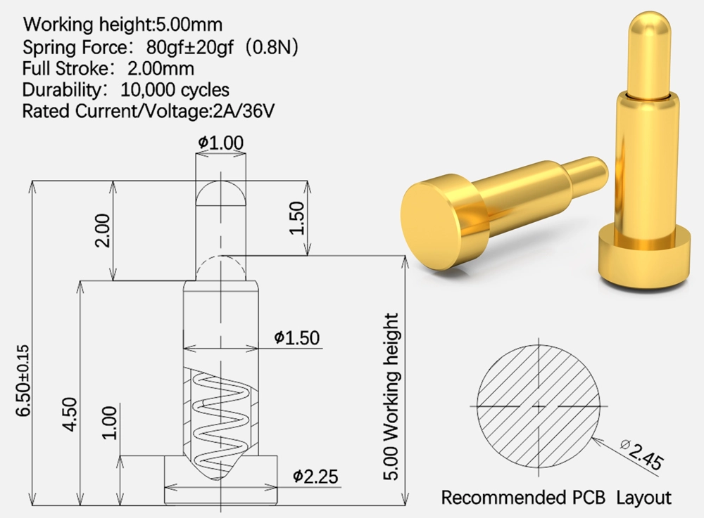
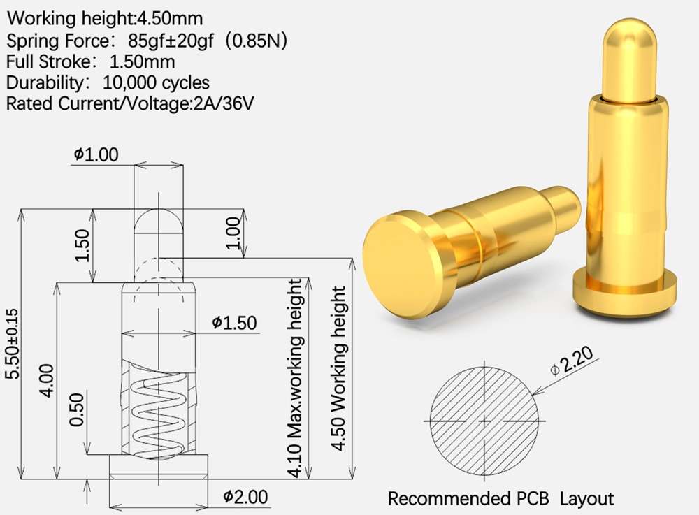
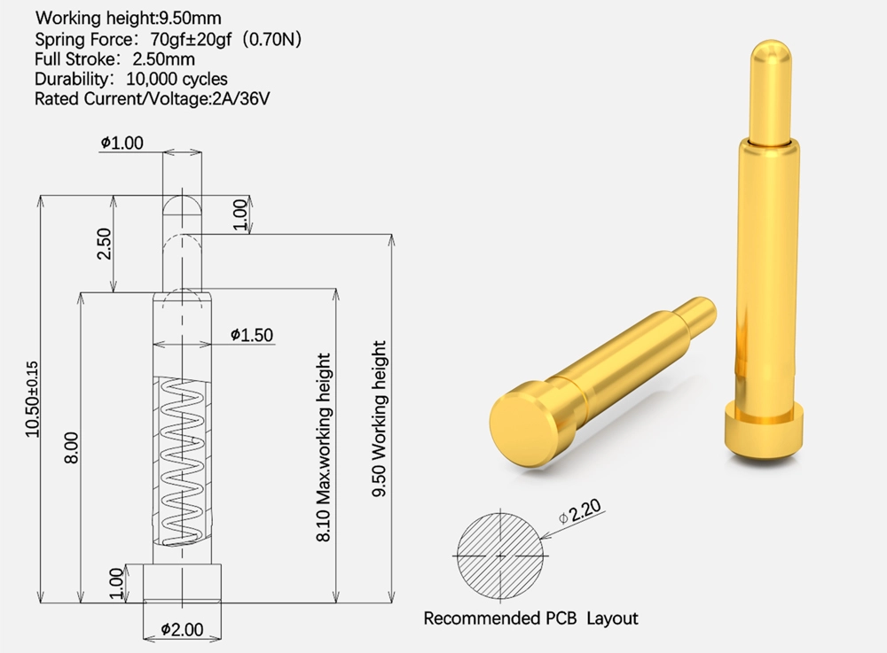
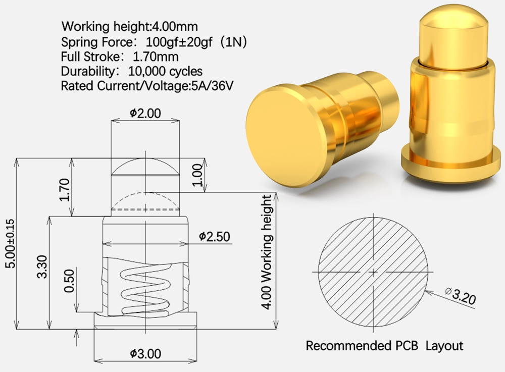
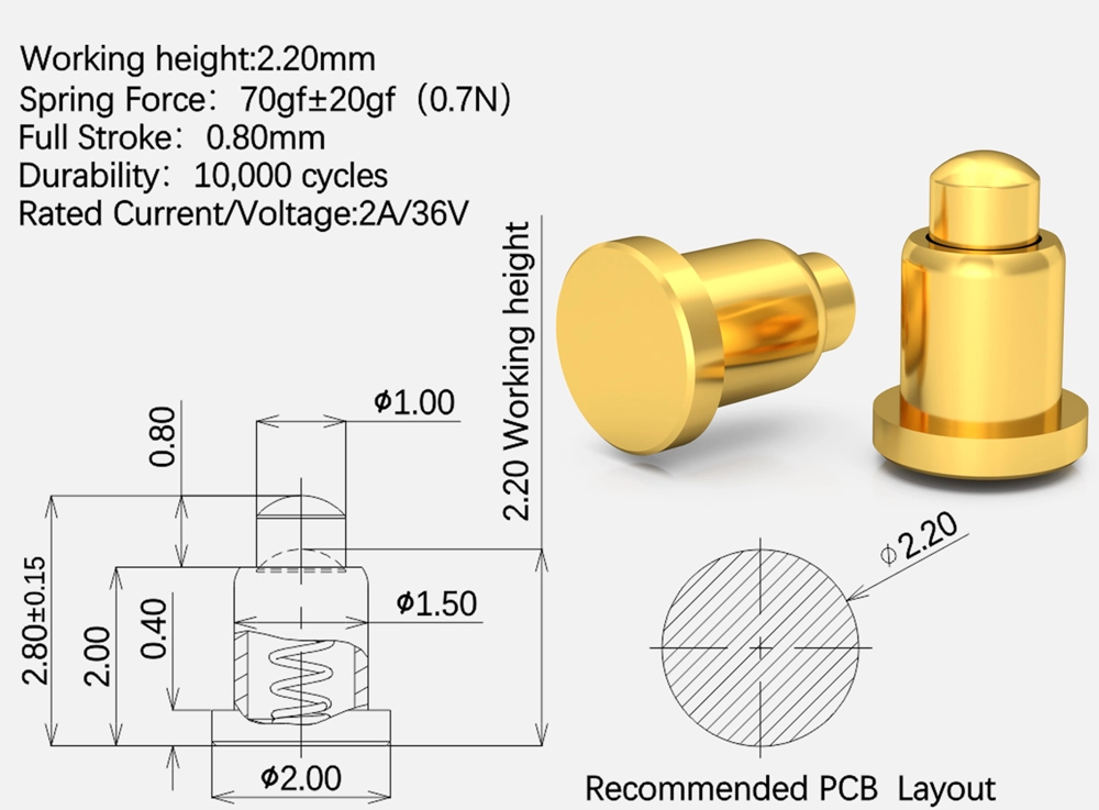
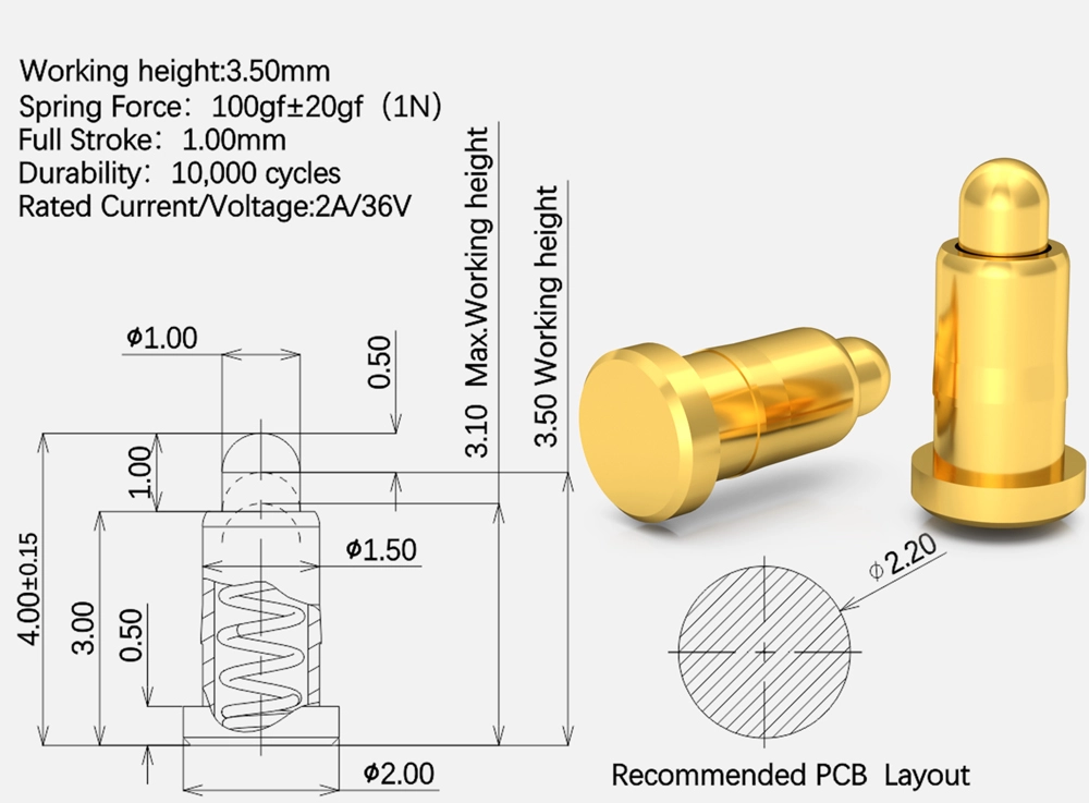
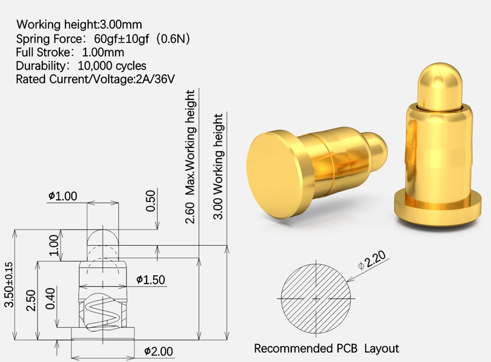
| Items | Details |
| Material | ● Plunger: Lead-Free Copper Alloy |
| ● Body: Lead-Free Copper Alloy | |
| ● Spring: Stainless Steel | |
| ●SolidPin: Lead-Free Copper Alloy | |
| Main Technical Parameters | ● Standard state: |
| ● Operating temperature: -40~+120°C(Standard) | |
| ● Operating humidity: 20-85%RH | |
| ● Storage temperature: -10~+50°C | |
| ● Storage humidity: 20-85%RH | |
| ● Rating voltage: 36V AC/DC(Standard) | |
| ● Rating current: 2A/Pin Continuous(Standard) | |
| ● Contact resistance: 30 mΩ Max.(Standard) | |
| ● Withstanding voltage: 250V AC ,1 Minute | |
| ● Insulation resistance: 500 MΩ Min. | |
| ● Durability:10,000 Cycle(Standard) | |
| ● Working Spring Force:40~120gf(Standard) | |
| Electroplating | ● Plunger: Ni Plating 1.4μm, Gold Plating 0.30μm |
| ● Body: Ni Plating 1.4μm, Gold Plating 0.10μm | |
| ● SolidPin: Ni Plating 1.4μm, Gold Plating 0.10μm | |
| Contact Type | ●Vertical Contact Type |
| Installation Method | ● SMT automatic placement machine+Reflow soldering |
| Environmental Protection Standard | ● Comply with EU RoHS and Reach standards |
Please Note: Please refer to the operation manual for instructions and precautions
| SN | Product Image | Full stroke | Initial Height | Working Height | Catalog Download |
| 1 |
| 0.4~0.8 | 1.80~3.10 | 1.50~2.60 | short-SMD Pogo Pins |
| 2 |
| 1.00 | 3.15~6.00 | 2.30~5.30 | 1.00-SMD Pogo Pins |
| 3 |
| 1.50 | 4.50~10.00 | 3.20~9.00 | 1.50-SMD Pogo Pins |
| 4 |
| 2.00 | 5.80~16.00 | 4.00~15.00 | 2.00-SMD Pogo Pins |
| 5 |
| 2.50 | 7.10~16.00 | 4.80~15.00 | 2.50-SMD Pogo Pins |
| 6 |
| >3.00 | 8.40~20.00 | 5.60~19.00 | >3.00-SMD Pogo Pins |
Contact
Rtench's Pogo Pin Connectors News
